Optimal design of heat sinks, especially for devices with high thermal loads such as MOSFETs and IGBTs, is critical to the efficient operation of these devices and to avoid premature component failure. This requires a combination of fans and heat sinks to provide adequate cooling for high-power devices that dissipate large amounts of heat.
Wenxuan Thermal Energy has professional customization capabilities and diversified application markets, and can customize cooling products for different systems for customers.
As shown in Figure 1, a shroud or duct is often used to direct the fan's airflow into the radiator to prevent airflow around the radiator, thereby reducing the effective cooling capacity of the fan and heat sink combination.

Figure 1: Heatsink and fan design without bypass
The optimal heat sink spacing and resulting thermal resistance for the fan/radiator combination shown in Figure 1 can be calculated directly using a few formulas to quickly estimate the required heat sink size.
However, it is not feasible to optimize the fin spacing of a heat sink assuming a constant flow rate or volumetric flow rate. The airflow speed between fins is determined by the fin spacing and their number, using Equation 1. This formula states that the air volume flow approaching the radiator is the same as the air volume flow passing through the radiator because there is no bypass flow around the radiator.

Figure 2: Air cooling fin dimensions

Vf:Air velocity between fins
V:Volume flow into the radiator
Hf=H-b:fin height
S:spacing between fins
Nf:number of fins
The smaller the fin spacing s, the higher the air velocity Vf between the fins. The higher the air flow rate, the better the cooling effect of the heat sink. If you want to optimize the size of the heat sink, the spacing between the fins should be a small value, because the air flow rate will increase as the fin spacing decreases, and the cooling effect will also increase. In practical applications, airflow is provided by fans or blowers. The flow rate is not constant and is limited by the increase in heat sink pressure drop as the heat sink spacing s decreases.
1.Heat sink design assumptions
To simplify the analysis and avoid significant calculation errors, we will make the following assumptions:
a.The surface area resulting from the fin thickness t and base thickness b is much less than the total surface area of the heat sink.
b.The heat source is the same length and width as the heat sink and is located in the center of the heat sink base.
c.The heat source and the base of the heat sink are in full contact with the fan or blower.
d.All airflow passes through the radiator.
e.Compared with convection, radiative heat transfer is small and can be ignored.
f.The airflow through the radiator is laminar and steady. The thickness of the heat sink is small compared to the spacing s between the heat sinks.
Assuming laminar airflow through the radiator works for most commercial radiator/fan combinations. In electronics, fan noise is a major consideration, so fan speed is intentionally reduced to avoid significant noise when transitioning from laminar to turbulent flow.
2.Calculate fan flow
The first step in designing a heat sink is to determine the operating point of the fan and heat sink combination. When a fan or blower is used with a radiator, the performance of the fan will depend on the design of the radiator.
As shown in Figure 3, each fan has a unique pressure/flow curve, where flow rate is inversely proportional to the pressure drop across the fan. Radiators also have a pressure/flow curve that is proportional to the pressure drop across the radiator, as shown in Figure 3. The flow through the fan/radiator combination is the intersection of the fan and radiator pressure/flow curves.

Figure 3: Fan and radiator pressure versus flow curves
Fan curves are generally provided by the fan manufacturer and are usually extremely non-linear. In many cases, the only fan performance data they provide is maximum flow and maximum pressure drop. To simplify flow calculations and accommodate situations where only maximum flow and maximum pressure drop are provided, a simple linear approximation of the fan curve can be expressed in Equation 2. In most cases, this linear approximation of the fan curve provides a reasonable estimate of the fan performance curve.

ΔPmax:Maximum fan pressure drop
Vmax:fan maximum volume flow
In the case of multiple fans used side by side (parallel), the maximum flow rate Vmax of the fan is the maximum flow rate of one fan multiplied by the number of fans.
The voltage drop across the heat sink is shown in Equation 3:

The air density ρ is calculated from the ambient air temperature.
The hydraulic diameter Dh of the channel between the fins can be approximated as 2s. The variables Kc and Ke are the pressure loss coefficients due to contraction and expansion of the airflow entering and exiting the radiator, respectively. The formulas for these pressure loss coefficients are a function of the frontal area σ=s/(s + t) and are based on the diagram provided in Reference 1.

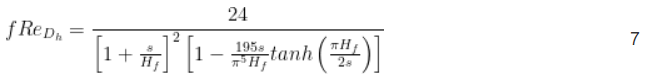
The apparent friction coefficient fapp is based on the model developed in reference [2]:

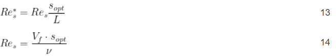
 , is the Reynolds number, where ν is the kinematic viscosity.
The term in Equation 6 takes into account the friction coefficient resulting from fully developed flow between the radiator fins. Fully developed flow occurs in very long channels, or in slow flows where the flow velocity profile remains constant.
To determine the fan/radiator operating point (i.e., the intersection of the fan and radiator pressure/flow curves), Equation 2 and Equation 3 are equalized and the unknown variable  is determined.

3.Optimize fin spacing
Calculate the fin spacing Sopt that provides maximum heat transfer using Equation 9, where μ and α are the viscosity and thermal diffusivity of air, respectively. This formula was proposed by Bejan et al. in Ref. 3.
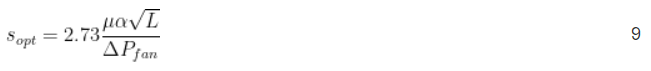
The optimal fin spacing Sopt is a function of fan pressure drop ΔPfan and heat sink pressure drop ΔPhs. The pressure of the entire system determines the flow rate picture through the radiator, and it is this flow rate that affects the heat transfer rate of the radiator.
Substitute Equation 9 for the fin spacing s in Equation 8 and determine the flow picture of the system by solving the resulting equation.
Please note that although Equation 8 solves ΔPfan and ΔPhs equal, only Equation 2 ΔPfan should be used when solving for flow in Equation 9. ΔPhs in Equation 3 depends on the fin spacing s, so using ΔPhs in Equation 9 to solve for the flow rate is mathematically intractable.
4.Calculate heat sink thermal resistance
From the solution of Equation 8, we know the flow picture and flow velocity Vf through the heat sink, and we can determine the heat transfer rate and thermal resistance of the heat sink.
Calculate the average heat transfer coefficient hf of the heat sink using Equations 10, 11, 12, 13, and 14 in Reference 4.
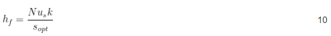
where k is the thermal conductivity of air.
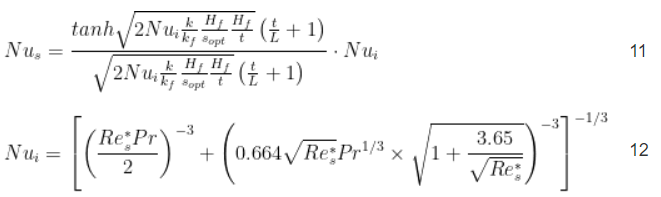
Pr is the Prandtl number of air, over the typical operating temperature range of heat sinks used in electronic cooling a value of 0.71 can be used.
Therefore, the total thermal resistance Rhs of the heat sink is:
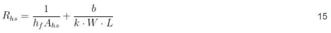
The wetted surface area of a radiator, Ahs, is the area in contact with the air flowing through the radiator.
The first term in Equation 15 is the thermal resistance of the heat sink, and the term after the plus sign is the thermal resistance at the base of the heat sink.

For diversified heatsinks, Wenxuan Thermal Energy has professional customization capabilities and diversified application markets, and can customize cooling products for different systems for customers. In the meantime, we will take many factors into account when designing the radiator and continue to optimize and improve the design of the radiator. If you have any other questions about heat sinks or need a cooling solution suitable for your business, please feel free to leave a comment or contact Wenxuan via email.
 English


